Hybrids 2024

The Rocketry Forum

Help Support The Rocketry Forum:

This site may earn a commission from merchant affiliate links, including eBay, Amazon, and others.
Interested in some thoughts from people who have experience with ABS, PVC - and even PS, PMMA - as Hybrid Fuels.

I've attached a paper that I've read many times, and continue to go back to - again and again. In my view, as a very experienced Physics, Chemistry, and Materials Lab Guy, this is particularly well done!!!

I don't want to criticize - at all!!! - anyone's fuel choice(s), what preloads are available, what preloads people are buying, using, have been using and - perhaps very importantly!! - are both experienced and comfortable with!!!

It seems to me that, from this paper, both Polyethylene and Polypropylene are really superior choices to ABS, PS, and PMMA. I'll start with the data for ABS, as it's clear to me that some of you - at least one of you!!! - is LIGHT YEARS AHEAD of me in terms of 'real' work, progress, experience, testing, development, engineering, knowledge, data taken, and - and - TEST FLIGHTS!!!

Material (abbreviated name), Qc (kJ/g) Δhc(kJ/g) Δhc/ro (kJ/g-O2)

Poly(acrylonitrilebutadiene-styrene) 39.84 38.07 13.04
Polystyrene (PS) 43.65 41.96 13.64
Poly(methylmethacralate) (PMMA) 26.75 24.99 13.02

While the first two quantities, and their units, may be familiar, the last quantity may be new. Here's what the author has to say: "The quantity, E = Δhc/ro is the heat released by combustion per unit mass of oxygen consumed in a fire where all combustion products are in their gaseous state. An accurate and representative value of E is thus important for calculating the heat released during flaming combustion of polymers
from oxygen consumption measurements."

And, now, Polyethylene and Polypropylene:

Polyethylene (PE) 47.74 44.60 13.01
Polypropylene (PP) 45.80 42.66 12.44

I know - but I don't really understand why!!! - that another factor here is Rho; the actual Fuel Density. One reason that I've been so interested in POM (Polyoxymethylene) is that it's Rho is 1.41 gm/cc.

My point here is NOT to say, "Hey, why are people using ABS, PS, and PMMA when both PE and PP seem 'better'!!!" But, if this data is any guide, it seems to me that both PE and PP are really good hybrid solid fuel choices, with PS as a clear # 3. Having said that - and admitting to being - again - way, WAY behind so many of you!!!! - I would really like to hear some thoughts, reactions, reasoning, comments, etc!!!

Thanks Everyone!!!
 

Attachments

  • Stanford Polymer HOC.pdf
    145 KB · Views: 0
Interested in some thoughts from people who have experience with ABS, PVC - and even PS, PMMA - as Hybrid Fuels.

I've attached a paper that I've read many times, and continue to go back to - again and again. In my view, as a very experienced Physics, Chemistry, and Materials Lab Guy, this is particularly well done!!!

I don't want to criticize - at all!!! - anyone's fuel choice(s), what preloads are available, what preloads people are buying, using, have been using and - perhaps very importantly!! - are both experienced and comfortable with!!!

It seems to me that, from this paper, both Polyethylene and Polypropylene are really superior choices to ABS, PS, and PMMA. I'll start with the data for ABS, as it's clear to me that some of you - at least one of you!!! - is LIGHT YEARS AHEAD of me in terms of 'real' work, progress, experience, testing, development, engineering, knowledge, data taken, and - and - TEST FLIGHTS!!!

Material (abbreviated name), Qc (kJ/g) Δhc(kJ/g) Δhc/ro (kJ/g-O2)

Poly(acrylonitrilebutadiene-styrene) 39.84 38.07 13.04
Polystyrene (PS) 43.65 41.96 13.64
Poly(methylmethacralate) (PMMA) 26.75 24.99 13.02

While the first two quantities, and their units, may be familiar, the last quantity may be new. Here's what the author has to say: "The quantity, E = Δhc/ro is the heat released by combustion per unit mass of oxygen consumed in a fire where all combustion products are in their gaseous state. An accurate and representative value of E is thus important for calculating the heat released during flaming combustion of polymers
from oxygen consumption measurements."

And, now, Polyethylene and Polypropylene:

Polyethylene (PE) 47.74 44.60 13.01
Polypropylene (PP) 45.80 42.66 12.44

I know - but I don't really understand why!!! - that another factor here is Rho; the actual Fuel Density. One reason that I've been so interested in POM (Polyoxymethylene) is that it's Rho is 1.41 gm/cc.

My point here is NOT to say, "Hey, why are people using ABS, PS, and PMMA when both PE and PP seem 'better'!!!" But, if this data is any guide, it seems to me that both PE and PP are really good hybrid solid fuel choices, with PS as a clear # 3. Having said that - and admitting to being - again - way, WAY behind so many of you!!!! - I would really like to hear some thoughts, reactions, reasoning, comments, etc!!!

Thanks Everyone!!!
Not all ABS is created equal. There are variations. But the big advantage it has is that you can print it. For me the objective is reasonable performance, reasonable cost and minimise the effort required. I can get 1 Kg of ABS fillament delivered to my door for Au$ 16. I can print any size reload. I dont need to put a large lathe anywhere.
YMMV.
 
What kind of combustion (in regards to O/F ratio) does E refer to? Probably stochiometric? If you look at the relationship between O/F and Isp you'll see that most hybrids run rather "rich". A combination of low O/F and high Isp is preferred because it allows you to use more fuel to achieve your desired thrust/impulse rather than using more nitrous. Nitrous doesn't have to great of a density when liquified under pressure and ~ambient temperatures leading to rather heavy hardware. That's also why high density fuels are preferred by many - you can just cram more of it in a smaller motor. TU Delft really pushed this, coming up with a formulation (Sorbitol/paraffin/Al) that has both a high density (~1,4) and high Isp (~200) at a very low O/F ratio (3:1).
 
What kind of combustion (in regards to O/F ratio) does E refer to? Probably stochiometric? If you look at the relationship between O/F and Isp you'll see that most hybrids run rather "rich". A combination of low O/F and high Isp is preferred because it allows you to use more fuel to achieve your desired thrust/impulse rather than using more nitrous. Nitrous doesn't have to great of a density when liquified under pressure and ~ambient temperatures leading to rather heavy hardware. That's also why high density fuels are preferred by many - you can just cram more of it in a smaller motor. TU Delft really pushed this, coming up with a formulation (Sorbitol/paraffin/Al) that has both a high density (~1,4) and high Isp (~200) at a very low O/F ratio (3:1).
Well, if you're basing your optimising metrics on things like dry mass, then you also have to consider the fuel's *core* in the density equations. So, often, when that's considered (especially for optimised short burn duration configs), your N2O bulk density is looking more attractive especially in cooler climates. However, there are other reasons to choose a more fuel rich mix like nozzle erosion/pitting.
Nevertheless, I'm of similar thinking to Norm, especially for my HPR stuff. Ease of manufacture is higher on my list of importance than performance. Saying that, we static tested a large N2O-HDPE hybrid last Friday, but that wasn't my typical run-of-the-mill HPR stuff.
If hybrids are to really become a serious contender for, say, orbital lift capability (and we could be in the infancy of something), 3D printing of fuel grains will be central to that success IMHO.

TP
 
Not all ABS is created equal. There are variations. But the big advantage it has is that you can print it. For me the objective is reasonable performance, reasonable cost and minimise the effort required. I can get 1 Kg of ABS fillament delivered to my door for Au$ 16. I can print any size reload. I dont need to put a large lathe anywhere.
YMMV.

I hadn't thought about that at all!! Thanks for point it out! So many clear advantages of being able to print Fuel Grains, Elements, etc!!

I do wonder, however, what the density of 3D Printed ABS is relative to that of stock (cast; extruded) ABS is? I would imagine that you do end up with a somewhat lower density 3D Printed ABS 'part,' no??

Did a super quick search: 1 kg PP 3D Printer Fiber - Polypropylene (PP) - for $40; 1 kg PE 3D Printer Fiber - Polyethylene (PE) - $60.
 
Not all ABS is created equal. There are variations. But the big advantage it has is that you can print it. For me the objective is reasonable performance, reasonable cost and minimise the effort required. I can get 1 Kg of ABS fillament delivered to my door for Au$ 16. I can print any size reload. I dont need to put a large lathe anywhere.
YMMV.
Good point about the Large Lathe!!!!
 
What kind of combustion (in regards to O/F ratio) does E refer to? Probably stochiometric? If you look at the relationship between O/F and Isp you'll see that most hybrids run rather "rich". A combination of low O/F and high Isp is preferred because it allows you to use more fuel to achieve your desired thrust/impulse rather than using more nitrous. Nitrous doesn't have to great of a density when liquified under pressure and ~ambient temperatures leading to rather heavy hardware. That's also why high density fuels are preferred by many - you can just cram more of it in a smaller motor. TU Delft really pushed this, coming up with a formulation (Sorbitol/paraffin/Al) that has both a high density (~1,4) and high Isp (~200) at a very low O/F ratio (3:1).

I think that you're right, in that E would refer to a Stoichiometric mix. I need to check that!! He does state, '... combustion per unit mass of oxygen consumed.'

Thanks for the note re "If you look at the relationship b/w O/F and Isp...." I think that one of the things that interests me in POM (Polyoxymethylene) as a fuel is your point re 'that's also why high density fuels are preferred by many -' It has a Rho of 1.41. In terms of that value, E, POM has the highest value of all Polymers tested and reported on in the paper.

Thanks for sharing the point/data re TU Delft. While I know POMs density, and that of PP, PE, PMMA, and PS - I think that there are 3D Printer Filaments of the latter two and I do know that POM can be 3d Printed(!!), I do not yet have any test results re Isp and O/F. (I am working on that!).

Thanks Again!
 
What kind of combustion (in regards to O/F ratio) does E refer to? Probably stochiometric? If you look at the relationship between O/F and Isp you'll see that most hybrids run rather "rich". A combination of low O/F and high Isp is preferred because it allows you to use more fuel to achieve your desired thrust/impulse rather than using more nitrous. Nitrous doesn't have to great of a density when liquified under pressure and ~ambient temperatures leading to rather heavy hardware. That's also why high density fuels are preferred by many - you can just cram more of it in a smaller motor. TU Delft really pushed this, coming up with a formulation (Sorbitol/paraffin/Al) that has both a high density (~1,4) and high Isp (~200) at a very low O/F ratio (3:1).

ok. Approximately 1 gram of a given polymer is placed in a sealed chamber with 99.99% pure O2 at 2 MPa; that's 290+ PSI. The volume of the test chamber (combustion test chamber; oxygen combustion vessel) is 350 ml. At 20-25 C., and 2 Mpa, that's .289 Moles of available O2. So, we have 8.96 gm O2 available for the complete combustion of 1 gm of Polymer. I think that it's safe to say it's an Oxygen Rich environment, and that, if there's no forced flow of O2, the polymer sample will combust (burn) in a ~ stoichiometric fashion.
 
I think that you're right, in that E would refer to a Stoichiometric mix. I need to check that!! He does state, '... combustion per unit mass of oxygen consumed.'

Thanks for the note re "If you look at the relationship b/w O/F and Isp...." I think that one of the things that interests me in POM (Polyoxymethylene) as a fuel is your point re 'that's also why high density fuels are preferred by many -' It has a Rho of 1.41. In terms of that value, E, POM has the highest value of all Polymers tested and reported on in the paper.

Thanks for sharing the point/data re TU Delft. While I know POMs density, and that of PP, PE, PMMA, and PS - I think that there are 3D Printer Filaments of the latter two and I do know that POM can be 3d Printed(!!), I do not yet have any test results re Isp and O/F. (I am working on that!).

Thanks Again!
I think the question is more about the void content than the density. Starting with the same molecular weight of PP for example, a cast or extruded sample has a void content around 0, for all practical purposes it is a true solid. For a 3d printed part, it is pretty difficult to print a thicker wall part with a porosity of less than about 3% where 5% is a reasonable number. (from test data..).

So here is the thing I have really wondered about, for a solid motor porosity bad.... but for a hybrid fuel grain? Some porosity specifically in the inner diameter may be a good thing for the melt/sublimation of the PP. The thought is it would create flow turbulence on the surface, plus 'gas jets' as they pop.
In tests we did at UTK, a solid 3D printed ABS grain regressed ever so slightly faster than an identical grain machined from a solid piece of ABS. My best guess is the turbulence induced by the layer lines was the leading cause of the increased regression rate, but the porosity of the 3D printed grain was virtually zero (printed on a fancy Stratasys Fortus) so I can't say whether or not typical hobby prints would see an additional boost from porosity. In either case you are right in that hybrids don't really care that much about porosity, especially compared to solids. The regression process is sort of self-regulating, as discontinuities or opened voids will create local regions of increased regression rate where they will smooth themselves out (think of a wood plane).
 
I think the question is more about the void content than the density. Starting with the same molecular weight of PP for example, a cast or extruded sample has a void content around 0, for all practical purposes it is a true solid. For a 3d printed part, it is pretty difficult to print a thicker wall part with a porosity of less than about 3% where 5% is a reasonable number. (from test data..).

So here is the thing I have really wondered about, for a solid motor porosity bad.... but for a hybrid fuel grain? Some porosity specifically in the inner diameter may be a good thing for the melt/sublimation of the PP. The thought is it would create flow turbulence on the surface, plus 'gas jets' as they pop.

I remember some posts from Edward (alphahybrids) about using polyurethane foam as a binder to make very high regression grains.
 
In tests we did at UTK, a solid 3D printed ABS grain regressed ever so slightly faster than an identical grain machined from a solid piece of ABS. My best guess is the turbulence induced by the layer lines was the leading cause of the increased regression rate, but the porosity of the 3D printed grain was virtually zero (printed on a fancy Stratasys Fortus) so I can't say whether or not typical hobby prints would see an additional boost from porosity. In either case you are right in that hybrids don't really care that much about porosity, especially compared to solids. The regression process is sort of self-regulating, as discontinuities or opened voids will create local regions of increased regression rate where they will smooth themselves out (think of a wood plane).
Drew,

I need to find the report (not one of mine) but there is a theoretical minimum void content with FDM just based on the mechanics of it, think about laying tootsie rolls in parallel then laying another layer on top transversely to them, there is a small saddle that dosn't fill, slow speeds with small nozzle and low layer height got the void content down to something like 1.2% but typical numbers (faster speeds and thicker layer heights) gave about 3%. Im guessing much of the stuff on here is 5%voids.

Simple test, print a good sized part where you know the EXACT volume, or use water displacement to determine the volume, weigh the part and verify the density. I get around 1.23 density after annealing for PETG using a layer height of .2mm infill speed of 30mm/s outer wall of 18mm/s and a .4mm line width. Works out to be about 3.5% voids.

Mike
 
Drew,

I need to find the report (not one of mine) but there is a theoretical minimum void content with FDM just based on the mechanics of it, think about laying tootsie rolls in parallel then laying another layer on top transversely to them, there is a small saddle that dosn't fill, slow speeds with small nozzle and low layer height got the void content down to something like 1.2% but typical numbers (faster speeds and thicker layer heights) gave about 3%. Im guessing much of the stuff on here is 5%voids.

Simple test, print a good sized part where you know the EXACT volume, or use water displacement to determine the volume, weigh the part and verify the density. I get around 1.23 density after annealing for PETG using a layer height of .2mm infill speed of 30mm/s outer wall of 18mm/s and a .4mm line width. Works out to be about 3.5% voids.

Miketh 3D
While there is obviously an additional void content with 3D printing which may or may not be an issue there are significant advantages to printing.
I can choose any shape for the core, I can incorporate a spiral in the core, I only print the material I'm going to use and do not need to purchase various stock material sizes. I can vacuum-impregnate the voids with different materials.
So there are many advantages.

This is really truly remarkable to me!! While I don't have a 3D Printer, I do have a number of friends who do, and I've tried to keep generally abreast of the technology, it's capabilities, capacities, and quality and - because I'm a materials guy - the various polymers available to The Art!

Thanks for summarizing some of the capabilities and advantages; I don't think that anything that I've read before your note has SO MADE ME WANT TO BUY A 3D PRINTER!!!!!

The thought of simply printing identical Test Fuel Samples, in PP, PE, POM, PMMA, and PS (not to mention others!), and testing them all - under Identical Conditions! As am Empiricist - I'm certainly no great theoretician!! - this is really exciting!!

So, two questions:

1) Can someone recommend a 3D Printer that they really, really like? In general, I work with Right Circular Cylinder Fuel Elements, 2" in diameter, or less, and <= 5 inches in length.

2) If I were to provide the 3D Printer Polymer Filament, is there someone out there - anyone - who would, for some reasonable fee(!?), print some 5 different Physically Identical Test Parts for me!?!?

Thanks again!!
 
bambu labs p1s. Don't mess around. I've spent way more than that, by not spending that...... Plus when I started it didn't exist.... If you cannot afford it, find a way to afford it. Ditch the girlfriend.....
Edit:-
Just bought one on Amazon Au. There was a 20% off voucher Au$957 delivered..... Woo Hooo.
:)
 
Last edited:
bambu labs p1s. Don't mess around. I've spent way more than that, by not spending that...... Plus when I started it didn't exist.... If you cannot afford it, find a way to afford it. Ditch the girlfriend.....
Edit:-
Just bought one on Amazon Au. There was a 20% off voucher Au$957 delivered..... Woo Hooo.
:)
Yes! I've worked with Ultimakers and a creality for a while and we got a Bambu X1C to replace on of the Ultimakers... You could say they don't play in the same league but I'd say it's not even the same sport anymore :D
 
Thanks, Guys! In my case, there were 3 Girlfriends to 'ditch,' but, Hey; what can I say!?😂

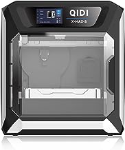
I just bought this:

Sponsored Ad - QIDI MAX3 3D Printer, High-Speed Large Size 3D Printers, 600mm/s Fast Print, Fully Auto Leveling, 65℃ Chamb...
Sponsored

QIDI MAX3 3D Printer, High-Speed Large Size 3D Printers, 600mm/s Fast Print, Fully Auto Leveling, 65℃ Chamber Heat, All-Around & High Precision Industrial Grade, Large Printing Size 12.8×12.8×12.4"

4.5 out of 5 stars
1,281
100+ bought in past month

$899.00

Got it for $799 USD.

I'm thinking of simply using TinkerCAD for the Fuel Element (Segment) design work; any suggestions here would be greatly appreciated.
 
In general, it does seem like these 2 Bambu Labs 3D Printers, the X1C and P1S, are, well, super duper!!! The one I found - after a good deal of research - will print all of the Polymers we've been discussing. Also - and this is an aside!! - I've always been interested in PVA (Polyvinyl Alcohol; Ethenol) as a potential fuel, and it can be 3D Printed.

Anyway, perhaps the one benefit, or advantage, of this QIDI unit is that the entire chamber can be heated to and held at up to 65 C. This, as I understand it, can be very helpful with some materials, some parts - depending on many factors. Seems to improve overall quality, layer-layer adhesion; and reduce voids, defects, etc.
 
What are the propper hoses and fittings to use for N2O for GSE? My Hypertek fill stem looks like it uses aluminum flared fittings,
20240617_174804.jpg

I'm not sure if I need braided SS hose etc to hook it up. Any resources to point to for building up a Hypertek and U/C valve type system would be appreciated.
 
What are the propper hoses and fittings to use for N2O for GSE? My Hypertek fill stem looks like it uses aluminum flared fittings,
View attachment 651360

I'm not sure if I need braided SS hose etc to hook it up. Any resources to point to for building up a Hypertek and U/C valve type system would be appreciated.
The blue fitting is a JIC (AN) fitting not to be confused with the flare connector that uses a faring tool on metal tube. The anodized aluminum ones work fine this would connect to a hose with a JIC fitting on it. I usually use brass fittings a bit more durable than aluminum, and all of them are high pressure fittings. I was helping out someone with their hybrid once, I stopped helping once I realized they had used off the shelf home depot fittings designed for water.

For my 'U/C' type I use a braided hose from the solenoid. I have standardized on AN-4 male (like you have in blue) connected to a compression fitting.

1718729084844.png


The hoses are off the shelf or can be made custom from a hose shop. I just showed a short piece but you got the idea. I have multiple sets of the 'top assembly' of the compression fitting (orange) and JIC -4 to 1/4 NPT. I buy multiple 'compression sleeves' they are single use everything else is reused. I do all the connections ahead of time at home, that way out on the range all I do is connect the JIC to the rocket.

Side Note, for larger rockets I use a 8 foot fill hose PLUS a 2 foot hose connected at the end closest to the rocket. The end can be damaged when the rocket releases the tube, I would rather replace a 2 foot one (or get the hose shop to make it a 1 3/4 foot one) than replace the longer hose. I keep a spare short one with me at the launch.

1718730017417.gif
1718730118851.gif
1718730311716.gif
 

Attachments

  • 1718730261494.gif
    1718730261494.gif
    14.6 KB · Views: 0
The blue fitting is a JIC (AN) fitting not to be confused with the flare connector that uses a faring tool on metal tube. The anodized aluminum ones work fine this would connect to a hose with a JIC fitting on it. I usually use brass fittings a bit more durable than aluminum, and all of them are high pressure fittings. I was helping out someone with their hybrid once, I stopped helping once I realized they had used off the shelf home depot fittings designed for water.

Thanks for the info. I know that for oxygen service, and nitrous especially, you need to use safe wetted materials, that are completely grease free. That's why I was asking here for what people like to use, as many hose materials (plastic and rubber) can be used as fuels in hybrids.

Do they make 'flashback arrestors' for nitrous, similar to what you would put in line on an oxy-fuel welding setup?

I don't mind spending extra, the main thing is I want this to be a safe and durable setup.
 
What are the propper hoses and fittings to use for N2O for GSE? My Hypertek fill stem looks like it uses aluminum flared fittings,
View attachment 651360

I'm not sure if I need braided SS hose etc to hook it up. Any resources to point to for building up a Hypertek and U/C valve type system would be appreciated.
Thanks for the info. I know that for oxygen service, and nitrous especially, you need to use safe wetted materials, that are completely grease free. That's why I was asking here for what people like to use, as many hose materials (plastic and rubber) can be used as fuels in hybrids.

Do they make 'flashback arrestors' for nitrous, similar to what you would put in line on an oxy-fuel welding setup?

I don't mind spending extra, the main thing is I want this to be a safe and durable setup.
I use teflon hose with stainless braid for mine, when I first stated with hybrids, the 'hot rod shop' told me that is what they use, been using them since.

At one point i wondered about using a flashback arrestor (I have an Oxy-Acetlyne torch that has them), never seen one used for hybrids at the scale we use and just let the idea drop. Remember the fill solenoid is closed when you ignite the preheater, cant get back to to the fill tank.

On the hypertek valve stem you have, the lower fitting (blue) is used for NOS, filling the flight tank (motor), the upper one (red) is used with oxygen, the ignition uses a high voltage source (i used to use a 12v transformer for neon tubes) and a spark gap. You fill the tank all the way, then close the fill solenoid and open the oxygen solenoid and turn on the high voltage source. What I dont se on your setup is a collar for the cable ties that hold it in place, these burn through, and lets the fill tube 'drop' letting the nitrous out into the oxygen burning grain - launch.

For the hypertek you need a nitrous solenoid (fill and dump) plus an oxygen solenoid and regulator. If it sounds a bit complicated, it is compared to a 'burn through' fill tube. I wouldn't recommend trying to launch a hypertek without having someone with experience helping / showing the technique the first time. . I did my Level 3 cert on a Hypertek M, but have moved over to 'easier' hybrids.
 
Last edited:
I use teflon hose with stainless braid for mine, when I first stated with hybrids, the 'hot rod shop' told me that is what they use, been using them since.

At one point i wondered about using a flashback arrestor (I have an Oxy-Acetlyne torch that has them), never seen one used for hybrids at the scale we use and just let the idea drop. Remember the fill solenoid is closed when you ignite the preheater, cant get back to to the fill tank.

On the hypertek valve stem you have, the lower fitting (blue) is used for NOS, filling the flight tank (motor), the upper one (red) is used with oxygen, the ignition uses a high voltage source (i used to use a 12v transformer for neon tubes) and a spark gap. You fill the tank all the way, then close the fill solenoid and open the oxygen solenoid and turn on the high voltage source. What I dont se on your setup is a collar for the cable ties that hold it in place, these burn through, and lets the fill tube 'drop' letting the nitrous out into the oxygen burning grain - launch.

For the hypertek you need a nitrous solenoid (fill and dump) plus an oxygen solenoid and regulator. If it sounds a bit complicated, it is compared to a 'burn through' fill tube. I wouldn't recommend trying to launch a hypertek without having someone with experience helping / showing the technique the first time. . I did be Level 3 cert on a Hypertek M, but have moved over to 'easier' hybrids.
A few pictures,

Rocket with (2) Ratt K hybrids, only picture I have showing the attachments at the pad. On each one you can see the setup in the drawing I sent. The red stuff over the hose helps protect the hose, it is insulation for hydraulic hoses, you can get it at McMaster. I dont use it for smaller stuff or for motors with a longer fill hose, the skyripper 54 and Ratt 65 have short fill hoses, the braided hose gets blasted and whipped on launch. Ignore the aluminum angle the hoses go through, it is just there to hold the hoses until both motors go.

1718736686884.jpeg
View of a Hypertek Launch Setup

This was a hypertek setup I had, it isnt great picture but all I have.

The horizontal bar has a slot in it to allow the drop tube to move in and out (larger or smaller diameter rocket) the square tube over the horizontal tube is just a guide for the fill tube so it drops straight and is retained. The lower diagonal is just overkill really not needed. I added the spring after seeing someones fill tube get hung up in the motor. It worked fine, I'm not sure If i really needed it. I did a bent lower tube instead of using a rt angle like yours had. I had someone ask if that was to prevent resistance at the bend when filling, actually was I had a bunch of steel tube, a bender and no rt angles when I assembled it.

The picture with the rocket shows the tube held in the rocket with a cable tie like you would for launch, the cable tie is directly in front of the tube
The picture without the rocket shows the tube 'dropped'

1718736835060.jpeg
1718737632552.jpeg
 
Last edited:
Thanks for the reply.

I did my L2 on a Hypertek hybrid, and have flown several 440cc and 835cc motors. I have an 'Earthquake' 2800cc 75mm L system that has never flown. I used the GSE that Wayne Mrazek setup for ROC in SoCal back then. I am familiar with how the Hypertek setup works, but the fittings, hoses, and solenoid selection I have not needed to mess with before.

I am looking at building up my own GSE, as I've already invested a lot in the Hypertek hardware, but have no way to fly them, currently. Those 'L' grains keep staring at me, just asking to be used. In fact, my L3 rocket (which was flown on a M1315) was designed to be able to use the 75mm Hypertek motor.

I'm a mechanical engineer, and I enjoy tinkering with stuff, so I should be able to figure out the small details, I was just looking for recommendations on where to start.

I have a 54mm min diameter CF rocket that was designed around the 835cc Hypertek engine. Once I get the GSE figured out, I plan on making a launch tower to wrap around it for that rocket.
Wayne was my L3CC for my Level 3, he passed away the week before my flight.

I have two wired 'ROC style GSE (pictures below grey box) , plus a Black Dog Rocketry one that are set up for Hypertek motors, plus I have a home-built wireless one (pictures below red box), plus working on a second rev of the wireless. The 'ROC Hypertek GSE' are pretty easy to make yourself using Cat5 wire a few resistors, and a few relays. Used DB-9 connectors. I have one if you want some details about it. Plus I have the cad files for the bezels I use for the home built system that uses stock PVC boxes from home depot.

AUT_1766.JPGAUT_1769.JPG

1718746038586.png
1718746067485.png
 
I have two wired 'ROC style GSE (pictures below grey box) , plus a Black Dog Rocketry one that are set up for Hypertek motors, plus I have a home-built wireless one (pictures below red box), plus working on a second rev of the wireless. The 'ROC Hypertek GSE' are pretty easy to make yourself using Cat5 wire a few resistors, and a few relays. Used DB-9 connectors. I have one if you want some details about it. Plus I have the cad files for the bezels I use for the home built system that uses stock PVC boxes from home depot.

Any details or schematics for the basic system would be greatly appreciated. I don't think I would fly enough to justify a wireless system. I was thinking of using CAT-5 cable and relays for whatever scratch built system I come up with, as it is cheap and readily available in long continuous lengths.

I know there were systems that had 'solenoid savers' that would reduce the current going into the solenoids after the initial opening, to reduce the heat load on them. A lot of nitrous solenoids are made for a few seconds of operation, followed by a cool off period. I will be using these in the desert, and filling an 'L' flight tank may take several minutes.
Picture of the Solenoid Saver

I used two resistors in parallel since I couldn't find the ones i wanted to use. Dont be confused by the two Caps, one goes to resistors that are out of frame to the right.


All wired in parallel

(2) 50W 30ohm wirewound reistors
(1) 15,000 uF 16 volt capacitor

Seems to work fine - for the wireless system, my board designer (son - avionics engineer) used a smaller cap, not sure about the resistors he used, but the one i show does work.


1718754618956.png
 
Picture of the Solenoid Saver

I used two resistors in parallel since I couldn't find the ones i wanted to use. Dont be confused by the two Caps, one goes to resistors that are out of frame to the right.


All wired in parallel

(2) 50W 30ohm wirewound reistors
(1) 15,000 uF 16 volt capacitor

Seems to work fine - for the wireless system, my board designer (son - avionics engineer) used a smaller cap, not sure about the resistors he used, but the one i show does work.


View attachment 651419
I use x2 33ohm 5W resistors in parallel (16.5 ohm) with x2 16V 10,000uF caps. I think you probably need higher capacity caps for discharge configurations than charge configs, but don't quote me on that :p
Depends on your solenoid valves too of course. Some pilot type valves use less than 1.5A to both open and retain.

TP
 
Back
Top